
Enterprise VLAN Design Fundamentals:
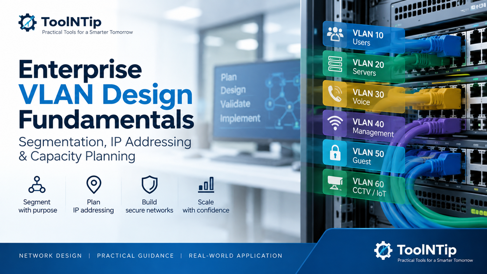
Enterprise VLAN Design Fundamentals: Segmentation, IP Addressing & Capacity Planning
A well-designed VLAN architecture does more than divide a network into smaller broadcast domains. It creates logical boundaries between systems with different purposes, security requirements, traffic patterns and operational responsibilities.
Whether you are designing a new office network, modernizing an existing environment or preparing an infrastructure expansion, VLAN planning should be approached as an architectural exercise rather than simply assigning VLAN IDs and subnets.
A practical VLAN design considers several questions together:
-
- Which devices and services should communicate directly?
-
- Which systems require isolation?
-
- How much address capacity does each network segment need?
-
- Where should routing and security policy be enforced?
-
- Which addresses should be dynamic, reserved or static?
-
- How much room should be retained for future growth?
-
- How will the resulting design be documented and maintained?
The goal is a network structure that is understandable, scalable and practical to operate.
What VLAN design is trying to achieve
A VLAN creates a logical Layer 2 network segment. Devices assigned to different VLANs normally require Layer 3 routing to communicate with one another.
That separation provides an opportunity to organize a network according to function rather than allowing every endpoint to occupy the same broadcast domain.
A structured design can help with:
-
- network organization;
-
- broadcast-domain control;
-
- security segmentation;
-
- access-policy enforcement;
-
- fault isolation;
-
- IP address management;
-
- troubleshooting;
-
- capacity planning; and
-
- future expansion.
The objective is not to create as many VLANs as possible. Every additional segment introduces addressing, routing, security and operational considerations.
The better objective is to create meaningful boundaries where the operational or security requirements justify them.
Start with requirements, not VLAN numbers
A common planning mistake is beginning with a spreadsheet of VLAN IDs.
Start instead by identifying the systems the network must support.
For example, an organization may require separate environments for:
| Segment | Typical purpose |
|---|---|
| Users | Employee desktops and laptops |
| Servers | Application and infrastructure servers |
| Management | Administrative interfaces for network and infrastructure equipment |
| Voice | IP phones and voice infrastructure |
| Corporate Wi-Fi | Managed wireless clients |
| Guest Wi-Fi | Visitor or untrusted Internet access |
| CCTV | Cameras and video-surveillance equipment |
| IoT | Embedded and smart devices |
| Printers | Shared printing devices |
| Storage | Storage networks or appliances |
| Security systems | Access control and other security infrastructure |
| DMZ | Services requiring a distinct security boundary |
Not every organization needs all of these VLANs. Conversely, larger environments may need several VLANs for a single broad function.
The segmentation model should follow the real environment.
Designing meaningful security boundaries
VLANs provide network separation, but a VLAN by itself is not a complete security policy.
Once two systems are placed in different VLANs, communication between them normally passes through a Layer 3 gateway. That creates a point where routers, Layer 3 switches or firewalls can apply policy.
Consider a management network as an example.
Network switches, wireless controllers, hypervisors and other administrative interfaces often require access from authorized administrator systems but should not necessarily be reachable from ordinary user or guest networks.
Separating management traffic into its own VLAN makes that policy easier to express.
The same principle applies to guest networks. Guest devices may need Internet access while requiring no access to internal corporate systems.
Segmentation therefore works best when the VLAN structure and the intended traffic policy are designed together.
VLAN ID planning
IEEE 802.1Q VLAN identifiers provide the numerical labels used to distinguish VLANs.
In practical network design, the important issue is not finding mathematically perfect VLAN numbers. It is creating a numbering scheme that remains understandable.
For example:
VLAN 10   Users
VLAN 20   Servers
VLAN 30   Voice
VLAN 40   Management
VLAN 50   Guest
VLAN 60   IoT
Another organization might reserve ranges:
10–99      User networks
100–199    Infrastructure
200–299    Voice
300–399    Wireless
400–499    Security / IoT
Either approach can work.
Consistency is more valuable than clever numbering.
Document the convention and avoid assigning VLAN IDs without understanding whether they are already used elsewhere in the Layer 2 environment.
Plan IP addressing at the same time
VLAN and subnet planning are closely related.
In a typical routed enterprise network, each VLAN is associated with an IP subnet. A design therefore needs enough address space for every segment while avoiding overlap.
Private IPv4 address space commonly comes from:
10.0.0.0/8
172.16.0.0/12
192.168.0.0/16
Choosing between them should consider the existing environment, organizational standards, routing architecture, VPNs, connected sites, cloud networks and potential address overlap.
A new network should not consume unnecessarily large ranges simply because private addresses are available. At the same time, allocating a subnet with almost no spare capacity creates avoidable redesign work later.
Understand subnet capacity
Subnet prefixes determine both the size of the network and the number of addresses available within it.
Examples include:
| Prefix | Total IPv4 addresses | Traditional usable host addresses* |
|---|---|---|
/30 |
4 | 2 |
/29 |
8 | 6 |
/28 |
16 | 14 |
/27 |
32 | 30 |
/26 |
64 | 62 |
/25 |
128 | 126 |
/24 |
256 | 254 |
/23 |
512 | 510 |
/22 |
1,024 | 1,022 |
*For conventional IPv4 LAN subnets where network and broadcast addresses are unavailable to hosts. Special-purpose networking can have different rules.
A VLAN requiring approximately 100 client addresses, for example, will generally not fit into a /26, which traditionally provides 62 usable host addresses. A /25 provides 126.
But selecting /25 solely because 100 devices fit today may still be too restrictive if substantial growth is expected.
Build in capacity headroom
Network designs should account for more than today’s device count.
A segment may grow because of:
-
- additional employees;
-
- new offices or departments;
-
- wireless expansion;
-
- IP phones;
-
- cameras;
-
- printers;
-
- virtual infrastructure;
-
- monitoring equipment;
-
- temporary devices;
-
- automation;
-
- new applications; or
-
- operational reserves.
If a network currently requires 110 addresses, designing for exactly 110 creates very little tolerance for change.
Capacity planning should therefore consider both current demand and reasonable future growth.
The appropriate amount of headroom depends on the environment. A stable infrastructure network may have different growth expectations from a rapidly expanding wireless or IoT environment.
Avoid excessive subnet allocation
Headroom does not mean every VLAN should receive a /16.
Oversized networks can waste address space, increase broadcast scope and make hierarchical address planning harder.
The goal is balance:
Allocate enough capacity for expected operation and growth without consuming disproportionately large portions of the available address plan.
This becomes especially important when many sites, departments, cloud environments or VPN-connected networks share a broader private addressing strategy.
Gateway planning
Devices normally require a default gateway to communicate outside their local subnet.
Organizations often adopt a predictable convention such as using the first usable address:
Subnet:   10.20.10.0/24
Gateway:  10.20.10.1
Other conventions are also valid.
The particular address is less important than applying the chosen convention consistently and documenting it.
Gateway design must also account for the actual network architecture. The gateway may exist on a Layer 3 switch, router, firewall, redundant gateway pair or another routing platform.
A planning tool can determine an appropriate address, but the implementation architecture determines where that gateway actually resides.
DHCP scope planning
Many endpoint VLANs use DHCP, while infrastructure segments may rely more heavily on static or reserved addresses.
A useful DHCP design distinguishes between:
-
- gateway addresses;
-
- infrastructure addresses;
-
- statically assigned systems;
-
- reserved addresses;
-
- dynamically allocated clients; and
-
- intentionally unused capacity.
For example, a /24 client VLAN might reserve a portion of the beginning of the subnet for infrastructure or static assignments and use the remaining range for DHCP clients.
The exact convention should match organizational requirements.
Static and reserved addressing
Not every address should necessarily come from a dynamic pool.
Systems commonly considered for static or reserved addressing include:
-
- gateways;
-
- network infrastructure;
-
- servers;
-
- controllers;
-
- printers;
-
- monitoring systems;
-
- security appliances; and
-
- other services that require predictable addressing.
The important point is to avoid accidental overlap between static assignments and DHCP pools.
Address reservations should be documented as part of the network plan.
Inter-VLAN routing
Creating VLANs does not determine which VLANs are allowed to communicate.
That decision belongs to the routing and security design.
A network might require:
Users → application servers        Allow required services
Users → management VLAN            Deny
Guest → internal networks          Deny
Guest → Internet                   Allow
Voice → call infrastructure        Allow required services
Administrators → management        Allow
IoT → selected services            Allow only what is required
These are policy examples, not universal rules.
The appropriate policy depends on the organization’s applications, trust model and security requirements.
The VLAN architecture should therefore document expected communication paths so firewall rules and access-control policies can be designed deliberately.
Consider east-west traffic
Not all important traffic travels toward the Internet.
Communication between internal VLANs—often called east-west traffic—can include application access, authentication, DNS, file services, monitoring, management and many other dependencies.
Overly restrictive segmentation without understanding those dependencies can break legitimate services.
Overly permissive routing can undermine the security value of segmentation.
Before deployment, identify which services need to cross each VLAN boundary.
Designing with an existing address space
Many projects do not start with an empty network.
You may already have an allocated range such as:
10.20.0.0/16New VLAN subnets must then fit inside the available address plan without overlapping existing networks.
Before allocating new ranges, identify:
-
- existing subnets;
-
- reserved ranges;
-
- remote sites;
-
- VPN networks;
-
- cloud networks;
-
- WAN addressing;
-
- routing summaries; and
-
- planned future allocations.
A design that works locally but overlaps a remote or VPN-connected network can create serious routing problems later.
When using ToolNTip VLAN Designer with an existing network, enter the applicable network prefix manually. A normal browser cannot reliably determine the IPv4 CIDR configured on your computer’s network interface.
Designing a new address space
A greenfield environment offers more flexibility.
Use that opportunity to create an addressing structure that can remain understandable as the network expands.
For example, address blocks might be organized by:
Site
→ function
→ VLAN
or:
Region
→ site
→ network segment
The precise hierarchy depends on the expected scale.
Where practical, structured allocation can also make routing summaries and documentation easier.
Voice networks
Voice endpoints are often placed into dedicated VLANs because they have distinct operational requirements.
Planning may need to consider:
-
- IP phone addressing;
-
- call-control infrastructure;
-
- DHCP options;
-
- QoS;
-
- voice gateways;
-
- security policy; and
-
- switch configuration.
A separate Voice VLAN helps organize those requirements, but VLAN separation alone does not configure QoS or telephony services.
Guest networks
Guest networks normally represent a lower-trust environment.
A typical design objective is:
Provide required external connectivity while preventing access to internal corporate networks.
Implementation may involve VLAN segmentation, firewall policy, wireless isolation, captive portals, DNS controls and other security mechanisms.
The VLAN is one component of that architecture.
Management networks
Management interfaces deserve deliberate treatment.
A management VLAN can contain interfaces for devices such as:
-
- switches;
-
- routers;
-
- wireless infrastructure;
-
- hypervisors;
-
- UPS systems;
-
- storage appliances; and
-
- other administrative platforms.
Access should generally follow the organization’s administrative trust model rather than simply being available to every user segment.
IoT and security-device networks
IoT, CCTV and physical-security devices often have communication patterns very different from normal user endpoints.
They may require access to a small set of controllers or cloud services while requiring little or no access to ordinary corporate clients.
Separating these systems can make those traffic policies easier to understand and enforce.
Avoid segmentation without purpose
It is possible to over-design a network.
Creating a separate VLAN for every small device category can lead to:
-
- excessive firewall rules;
-
- complicated routing;
-
- unnecessary DHCP scopes;
-
- larger configuration inventories;
-
- harder troubleshooting; and
-
- increased documentation burden.
Every proposed segment should answer a useful question:
What operational, security, traffic or administrative requirement justifies this boundary?
If there is no meaningful answer, another VLAN may not be necessary.
Document the design
A usable VLAN plan should document more than VLAN IDs.
At minimum, consider recording:
| Item | Example |
|---|---|
| VLAN name | Management |
| VLAN ID | 40 |
| Subnet | 10.20.40.0/24 |
| Prefix | /24 |
| Gateway | 10.20.40.1 |
| DHCP | Disabled or defined scope |
| Purpose | Infrastructure management |
| Expected capacity | 60 devices |
| Routing/security notes | Admin networks only |
| Site/environment | Headquarters |
Good documentation reduces dependence on institutional memory.
It also makes later troubleshooting and expansion much easier.
Validate before deployment
Before implementing the design, verify:
-
- every VLAN ID is appropriate and non-conflicting;
-
- subnet ranges do not overlap;
-
- each subnet has sufficient capacity;
-
- gateways fall inside the correct subnet;
-
- DHCP scopes do not conflict with reserved/static addresses;
-
- required infrastructure addresses have been reserved;
-
- inter-VLAN communication requirements are understood;
-
- management and guest boundaries match security policy;
-
- connected-site, VPN and cloud ranges do not overlap;
-
- future growth has been considered; and
-
- the final architecture has been documented.
Automated validation can catch structural problems, but it cannot determine every organizational requirement.
Technical review remains essential.
Use VLAN Designer to turn requirements into a plan
ToolNTip VLAN Designer is designed around this requirement-first approach.
Rather than starting with a blank addressing spreadsheet, you can define the network segments and approximate capacity you require, choose an addressing strategy, and generate an initial architecture for review.
The application can help organize VLAN IDs, subnet allocations, gateways, DHCP information and capacity while providing dashboard, table, card and advanced views of the resulting design.
You can then validate and refine the architecture and export the result for documentation or implementation planning.
Comments
Join the discussion
Sign in or create an account to participate.