
How to Design a VLAN Architecture with ToolNTip VLAN Designer
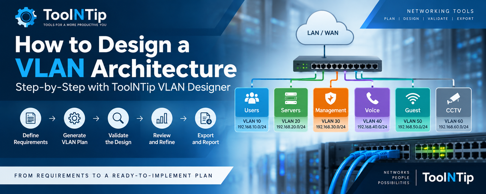
How to Design a VLAN Architecture with ToolNTip VLAN Designer
Designing a VLAN architecture involves more than assigning VLAN IDs. You also need to consider network segmentation, address capacity, subnet allocation, gateways, DHCP scopes and the communication requirements between different parts of the network.
ToolNTip VLAN Designer helps organize these requirements into a structured network plan that you can review, modify, validate and export before implementation.
This guide walks through the complete process.
Before You Begin
Before opening VLAN Designer, gather the basic information about the network you intend to design.
You should have an approximate idea of the types of network segments you require and the number of devices each segment needs to support.
For example, your network might include:
-
- Users
-
- Servers
-
- Management
-
- Voice
-
- Corporate Wi-Fi
-
- Guest Wi-Fi
-
- CCTV
-
- IoT
-
- Printers
-
- Other specialized networks
If you intend to design within an existing IPv4 address space, also have the applicable network prefix available, such as 10.20.0.0/16.
A normal web browser cannot reliably determine the IPv4 CIDR configured on your local network interface, so VLAN Designer requires you to enter an existing network prefix manually when that information is needed.
For a deeper explanation of the planning principles behind these decisions, read Enterprise VLAN Design Fundamentals: Segmentation, IP Addressing & Capacity Planning.
1. Open VLAN Designer
Open ToolNTip VLAN Designer in your browser.
The application runs as a guided network-design workflow. You can progress from your initial requirements to a generated VLAN architecture without installing network-planning software on your computer.
Opening VLAN Designer
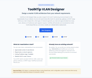
ToolNTip VLAN Designer initial network planning screen
2. Enter Organization and Project Information
Begin by entering the organization and contact information requested by the application.
Use meaningful project information so the finished design and generated report can be identified later.
This information is particularly useful when the resulting VLAN plan will be reviewed by another administrator, consultant or implementation team.
Complete the required fields and correct any validation messages before continuing.
Screenshot 2 — Organization and project information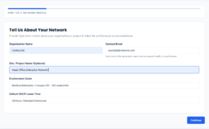
Organization and project information in ToolNTip VLAN Designer
3. Define Your Network Requirements
Next, describe the environment you are planning.
Think about what the network needs to support rather than beginning with arbitrary VLAN numbers.
A small office might require only a few logical segments, while an enterprise environment may require separate networks for users, servers, management systems, voice, wireless clients, cameras, IoT equipment and other infrastructure.
The objective is to describe the actual network requirements first. VLAN IDs and subnet allocations can then be built around those requirements.
4. Select the Network Segments You Need
Choose the predefined network segments that apply to your environment.
Only select segments that have an operational, security, traffic-management or administrative purpose.
For example, separating a management network from ordinary users can provide a useful boundary for later access-control policies. Similarly, a guest network can be isolated from internal corporate systems.
You do not need to select every available segment.
Screenshot 3 — Selecting network segments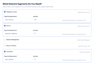
Selecting VLAN network segments in ToolNTip VLAN Designer
5. Add Custom Network Segments
If your environment requires a network that is not represented by the predefined options, add a custom segment.
Give it a descriptive name that communicates its purpose.
Examples might include:
Building Automation
Research Lab
Storage
Access Control
Development
Avoid creating custom VLANs merely to increase the number of segments. Each network boundary should have a practical reason to exist.
Screenshot 4 — Custom segment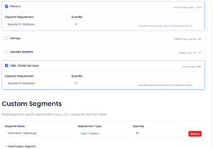
6. Enter Capacity Requirements
Estimate how many devices or addresses each segment must support.
Capacity is important because it influences the subnet size required for each VLAN.
Do not design only for the exact number of devices connected today. Consider reasonable future growth, additional infrastructure, temporary devices and operational reserves.
At the same time, avoid unnecessarily oversized networks.
VLAN Designer uses these requirements to help produce an address plan appropriate for the requested capacity.
Screenshot 5 — Capacity requirements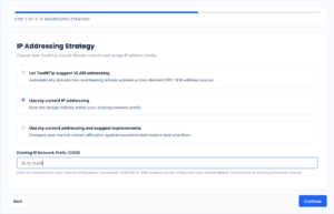
Entering VLAN capacity requirements for network segments
7. Choose an IP Addressing Strategy
VLAN Designer supports different approaches depending on whether you are creating a new address plan or working with an existing environment.
Recommended Addressing
Use the recommended approach when you want VLAN Designer to help establish an appropriate private address plan from the requirements you entered.
This is useful for new or relatively flexible environments.
Existing Addressing
Choose the existing-address-space workflow when the VLANs must fit inside a network prefix already assigned to the environment.
You will need to provide that prefix manually.
For example:
10.20.0.0/16
Before using an existing range, make sure you understand other allocations that may already exist within it.
Hybrid Addressing
Use the hybrid workflow when the design combines existing addressing constraints with new allocation requirements.
Whichever approach you choose, the resulting network plan should still be checked against connected sites, VPN ranges, cloud networks and other routed environments before deployment.
Screenshot 6 — Addressing strategy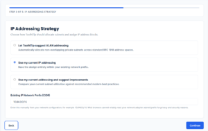
IP addressing strategy options in ToolNTip VLAN Designer
8. Enter the Existing CIDR When Required
If you selected a workflow based on an existing network, enter its IPv4 network prefix.
For example:
10.20.0.0/16
Enter the network prefix, not simply the IP address assigned to your computer.
VLAN Designer validates the information before using the address space for the generated architecture.
Remember that browser security restrictions prevent the application from reliably discovering the CIDR configured on your network adapter automatically.
9. Generate the VLAN Design
After reviewing your requirements, generate the design.
VLAN Designer processes the information and constructs an initial architecture based on the selected segments, capacity requirements and addressing strategy.
The generated result should be treated as a planning baseline, not an automatically deployable configuration.
Review it before implementation.
Screenshot 8 — Generated VLAN architecture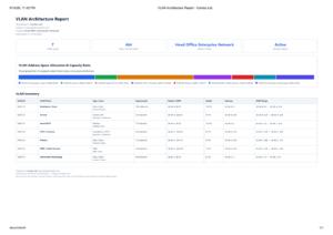 .
.Generated VLAN and subnet architecture in ToolNTip VLAN Designer
10. Review the Dashboard
Start your review with the dashboard.
The dashboard provides a high-level view of the generated architecture and helps you understand the overall structure before examining individual VLANs.
Check that the number and purpose of the generated network segments correspond to the requirements you entered.
11. Review the Address Allocation Graph
Use the address-allocation visualization to understand how the available address space has been distributed.
This is particularly useful when several VLANs with different capacity requirements are being allocated from a broader network prefix.
Look for allocations that appear unexpectedly large or small and confirm that the overall address plan leaves appropriate room for future requirements.
12. Review VLANs, Subnets, Gateways and DHCP Scopes
Examine the detailed network information produced for each segment.
Pay particular attention to:
-
- VLAN name and VLAN ID
-
- Network/subnet
-
- Prefix length
-
- Address capacity
-
- Default gateway
-
- DHCP information
-
- Segment purpose
Confirm that subnet ranges do not overlap and that each network has sufficient capacity.
Gateway addresses should fall within their corresponding subnet, and DHCP ranges should not conflict with addresses intended for gateways, infrastructure, static systems or other reservations.
13. Edit and Refine the Architecture
A generated design is a starting point.
If the initial result does not match your operational requirements, modify the applicable requirements or configuration and refine the design.
For example, you may discover that a segment requires more capacity, that a custom network should be added, or that an allocation should be reconsidered.
Iterative refinement is preferable to deploying a generated architecture without review.
14. Validate the Design
Run the application’s validation checks after making your changes.
Validation can help identify structural problems in the VLAN and address plan.
Before accepting the architecture, confirm that:
-
- VLAN IDs are appropriate
-
- subnet ranges do not overlap
-
- subnet capacity is sufficient
-
- gateways are valid
-
- DHCP allocations are appropriate
-
- required addressing information is complete
Automated validation cannot determine every operational or security requirement, so technical review remains necessary.
Screenshot 9 — Validation result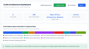
Suggested alt text: VLAN architecture validation results in ToolNTip VLAN Designer
15. Review the Different Design Views
VLAN Designer provides multiple ways to inspect the architecture.
Table View
Use the table when you need a compact comparison of multiple VLANs and their addressing information.
Card View
Card view provides a more separated visual representation of individual network segments.
Advanced View
Use the advanced configuration view when reviewing or refining more detailed aspects of the generated architecture.
Switch between the views according to the task you are performing rather than treating one view as the only representation of the design.
Screenshot 10-11 — Design views
16. Export the Design as JSON
Use the JSON export when you need a structured machine-readable representation of the VLAN design.
JSON can be useful for further processing, integration work, archival purposes or technical workflows.
Review exported data before using it in another system.
17. Export the Design as CSV
CSV provides a convenient tabular representation that can be opened in spreadsheet applications or incorporated into network documentation.
It is useful when the VLAN plan needs to be reviewed or supplemented by other teams.
18. Copy the Design to the Clipboard
For quick transfer into documentation, tickets, notes or another application, use the clipboard function where appropriate.
After copying, paste the result into the destination and verify that the expected information was transferred.
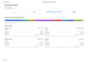
19. Generate a Printable or PDF Report
VLAN Designer can transform the active design into a cleaner report intended for documentation and review.
The report includes the relevant design information rather than simply printing the interactive application controls.
Depending on the active design, the report can include the dashboard, address-allocation visualization, organization/project information and the current architecture view.
Use your browser’s print workflow to print the report or save it as a PDF.
20. Perform a Final Technical Review
Do not move directly from generation to production deployment.
Before implementing the architecture, verify the design against the actual network environment.
Check for existing VLAN IDs, address overlaps, connected sites, VPN networks, cloud networks, routing requirements, security policies, DHCP infrastructure, switch and firewall capabilities, voice requirements, redundancy and any vendor-specific limitations.
Also document the intended communication between VLANs.
For example, a guest VLAN may require Internet access while being denied access to internal networks. A management VLAN may need to be reachable only from authorized administrative systems.
VLAN Designer helps plan the architecture; it does not configure switches, routers, firewalls or DHCP servers automatically.
VLAN Design Checklist
Before considering the plan complete, confirm that:
-
- Every required network function has an appropriate segment.
-
- Every VLAN has a clear purpose.
-
- VLAN IDs do not conflict with the target environment.
-
- IP subnets do not overlap.
-
- Each subnet has adequate current and future capacity.
-
- Gateway addresses are valid.
-
- DHCP and static/reserved addressing do not conflict.
-
- Existing, remote, VPN and cloud networks have been considered.
-
- Required inter-VLAN communication has been documented.
-
- Security boundaries match the intended trust model.
-
- The final architecture has been validated and documented.
-
- A qualified technical review has been completed before implementation.
- Learn the VLAN Design Principles
If you want to understand the architectural decisions behind segmentation, subnet sizing, capacity headroom, gateways, DHCP and inter-VLAN routing, read:
Enterprise VLAN Design Fundamentals: Segmentation, IP Addressing & Capacity Planning
Ready to Design Your VLAN Architecture?
Define your network requirements, plan your address space, generate the VLAN architecture, validate the result and export the finished design for documentation and implementation planning.
Comments
Join the discussion
Sign in or create an account to participate.